Generator to Alternator Conversion for the 12volt Type III
By Toby Erkson, ©1997-2005, All Rights Reserved.
Revised 11Dec2003
The stock Volkswagen electrical charging system is comprised of a 12volt, 30amp generator with an external voltage regulator. This system works great for the stock vehicle but begins lacking as soon as additional electrical items are added. Higher wattage headlamps, a modern stereo system (especially one with a big amplifier) and an aftermarket ignition system can begin to take its toll on the stock charging system over time. Also, generators have many weaknesses compared to alternators. Even VW knew this and began replacing the generator on the Type I (the Beetle) with an alternator. Even the Type IV came stock with an alternator (the VW 411, 412 and late Bus and the Porsche 914). In fact, this is a common kit and many Bug owners convert their charging system as a matter of course. Unfortunately, doing the same conversion for the Type III (the Fastback, Notchback and Squareback models) is more difficult as there isn't as much room to work with under the deck lid.
At the time of this writing my '72 Squareback is a custom vehicle and moving ever further from stock. The headlamps are 55watt Halogens, the stereo is a 30watt Sony, a red neon light license plate frame for a third brake light, a car alarm system (a small current draw except when the siren is activated), an air horn system that is fuse protected at 20amps and my ignition system is powered by a Jacobs Electronics Bug-Pak computerized ignition module that draws 4 to 8amps. My generator is good as is my voltage regulator and my battery is less than a year old. I checked my charging system and it's in good, functional shape. But a little while after I got my new ignition system I noticed that when I would drive with my lights on my generator light would faintly glow at idle and wouldn't go out until I was higher up in the RPMs. At the time I was driving with my lights on all of the time, as it was dark when I went to work and when I came home. It seemed that I was just over-taxing my stock charging system. Something needed to be done.
The only alternator conversions I had seen for the Type III consisted of a Type I alternator that required some trimming of the cooling tin as it is larger than the Type III generator. My goal was to find a simple, non-butchering, bolt-in installation that provided greater charging capabilities using an alternator. I drove to a starter/alternator/generator shop, removed my generator, walked in to the shop, put my generator on the counter and asked the person if he had a 12volt alternator that put out over 30amps AND that was the same size or smaller than my generator. He pointed to a little alternator on the shelf next to me. Gee, I was hoping for a little more adventure but I guess this was going to be simpler than I thought!
So, let's begin!
Although I wasn't able to satisfy all of my goals for this project (it's not a direct bolt-in) nonetheless it is an easy project for the majority of people who are comfortable working on their VW. If you can adjust your own valves, change the oil, replace the brake pads and drum shoes and even replaced the generator brushes then this will be a simple conversion. If you don't quite feel up to the challenge then I suggest you find a good, VW knowledgeable friend or mechanic and give them a printout of these instructions. The conversion will take less than half a day and even shorter if you are working in a professional garage with all the neat tools that they possess! I created this conversion at my apartment under my carport with basic tools so a garage isn't necessary.
What you will need:
12volt, 40amp Nippondenso alternator, part number 100211-1680 (see Image 1.)
Alternator belt, part number is Goodyear 15391
36" aftermarket battery cable with a post hole at each end (don't get the clamping kind like on the battery)
rubber mallet to help mold the hold down strap to the alternator shape
basic hand tools (mainly some box wrenchs and a socket set)
wire stripper and connection crimper tool
a couple of male and female wire connectors with sheaths
wire wrap ties
14cm of 12.7mm (1/2inch) fuel/emission line to insulate the battery cable from the deck lid
a small sheet of 1.5mm aluminum or sheet metal
tin snips, maybe even a hack saw (for cutting the aluminum or sheet metal)
a metal file to help dull the edges on the sheet metal parts that you cut
drill with 1/2 inch and 5/16 inch drill bits
2 studs, 5cm in length with 6mm non-threaded center section or similar (taken from a VW tranny)
read ALL of the directions first before proceeding -- it'll keep the surprises to a minimum!
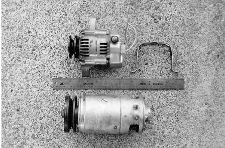 Image 1.
- Remove the ground battery cable from the battery.
- Remove the ground battery cable from the battery (yes, you'll probably loose your radio station presets, but do it!).
- Did you make sure you removed the ground battery cable? You don't want any sparks jumping around causing stray gas fumes to ignite, pitting various metal components and frying your voltage regulator, generator or alternator.
- Okay, after you remove the above mentioned battery cable you may proceed to step 5.
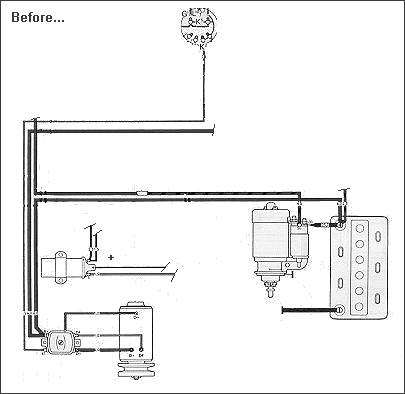
- Since you're under the back seat let's take care of the idiot light connection (for further assistance see the wiring diagrams at the end of this document).
- Remove the green and blue wires from the voltage regulator (located on the floor on the left side).
- Since both of these are female connectors you will need to join them by putting a double male spade connector between them or you can cut one of them off and crimp on a male connector or you can go extreme and cut off both connectors, solder them together and tape, coat or heat shrink the joint with electrical insulation. However you do it you want to connect the two. The first method is preferred if you ever plan on using the generator again. See Image 2.
- If you plan on removing the voltage regulator remember that you must keep the two big red and white wires connected (and insulated) so the fuse panel will get electricity. All of the other wires (except the idiot light) can then be removed.
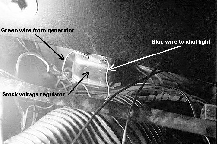 Image 2.
- Disconnect all wires from the generator.
- Take the big red and white striped wire and wrap the end with electrical tape and tuck out of the way. Do the same for the brown ground wire. This allows you to hook the generator back up if something should go awry. Of a matter of course you can always remove these wires for a cleaner looking set up. The green wire is the idiot light wire (for our purpose, that is) and we will be using it.
- Unbolt the generator strap and remove. You can now remove the generator and belt and set the generator/housing seal aside as you will use it on the alternator. Seal the generator and the belt (if it's still good) in a zipper freezer bag, date it and put any additional comments as needed (brushes new, belt has 1200 miles, etc.) and store it or give it to a purest -- never throw away Type III parts as they're getting more difficult to come by! While we're removing stuff go ahead and remove the pig tail from the back of the alternator so it won't get in the way (it has the two wires coming out of it).
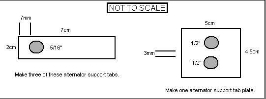
- Since the hold down strap studs will need to be replaced squirt some penetrating oil on them so it'll be easier to remove them. Okay, now it's time to make the mounting pieces. You want to make them with the generator off so you can make any minor adjustments. Use the below diagram to cut the metal. Make sure all of the holes are centered in the metal. Please excuse the standard measurements for the hole diameters but I didn't have any metric drill bits.
- The alternator support tab plate will fit inside the opening where the generator received its cooling air. The alternator will be receiving its cool air from here as well which is the reason for drilling the holes. The plate itself is used as a resting place for the alternator support tabs. Go ahead and fit the plate in the opening. This will help prevent you from dropping tools into the fan housing (like what I did with a socket extension (DOH!).Place the alternator support tabs over the studs and mold them over the generator mounting as shown in the below diagram. The diagram is an exaggeration so you will have a better idea of how the support tabs should be molded. As you can see in Image 3 the angles aren't very extreme. Notice that you need to put two support tabs on the left stud (Image 3.).
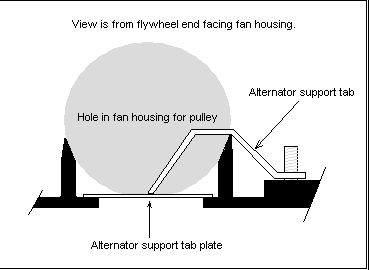
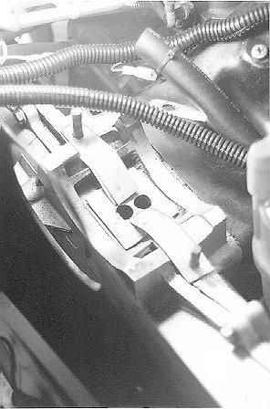 Image 3.
- Now it's time to replace the hold down strap studs with longer ones. The right stud doesn't really need to be replaced but for a proper set up I recommend it as it will make the strap adjustments easier.
- If you have a stud remover socket or such then just remove the studs and replace with the longer ones and continue with step 11 otherwise you're like me and you don't have a nifty stud remover, so...
- Take the nuts that you removed from the strap hold down studs and put both of them on a stud so they are touching each other and the top nut is below the top of the stud.
- Tighten the nuts against each other. You can do this with two 13mm wrenches or a 13mm wrench and crows foot. I recommend using a crow's foot because it makes the task easier.
- Once you have the nuts really tight put your crows foot (or wrench) on the bottom nut and turn it counter clock-wise like you were removing a screw. The top nut will keep the bottom nut from turning so the nuts will bite into the stud and it will turn (aren't you glad you listened to me and put that penetrating oil on before hand?). Image 4 illustrates this method but you will need to use a longer extension to clear the fan housing.
- When the stud comes out remove the nuts and repeat this process on the other stud.
- Now put the nuts on one of the long studs, tighten them against each other then thread the stud into the opening. When it becomes tight put the crows foot (or wrench) on the top nut and turn it clock-wise like you were inserting a screw.
- Once the stud is secured remove the nuts and repeat this process on the other stud.
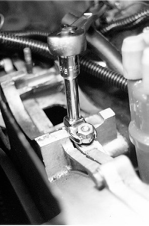
Image 4.
- Okay, you can now place all of the pieces for the alternator support in their proper places and place the alternator on the supports with the pulley inside the fan housing. Move the alternator around a little to get a feel of how it's going to sit. You may need to adjust and level the support straps so the alternator won't rotate.
- Take the generator boot and put it between the fan housing and alternator just like you were installing it on the generator. Notice how close the alternator must be to the fan housing! The rubber boot will fit on the fan housing and the alternator pulley face -- you will have to push the bottom of the boot down a little from the inside of the fan housing to get it to seal properly on both sides. Don't worry about it staying for now you just want to place the alternator in the correct position so you can mold the hold down strap to the alternator form.
- Using the rubber mallet and an anvil mold the generator hold down strap to the shape of the alternator. This isn't something I can easily explain so look at Images 1 and 5 to get an idea of what it should look like. You could even use the alternator a tad for the molding process but I wouldn't recommend doing all of the pounding on it! Just make sure that the right side can easily fit on the stud and the left side can at least have a few threads from the stud poke through.
- When the bracket molds to the body of the alternator fairly well go ahead and place the strap on the alternator but don't secure it yet. Now install the alternator belt; crank pulley first then the alternator pulley.
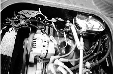
Image 5.
(The boot shown here is actually in backwards but it works just as well)
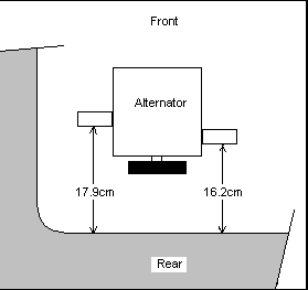 Image 6.
- Now tighten down the right side of the alternator strap then the left side just a little (don't forget to use a washer between the nut and the hold down strap). Adjust the alternator so the rubber boot makes a fairly good seal on the fan housing and the alternator. The alternator seal won't be like it was on the generator so don't expect a really good seal. Adjust the alternator so it's sitting level and pointing straight back. Space the alternator from the very edge of the engine bay opening as shown in Image 6. This is just a rough beginning to get it spaced. Once the installation is complete you may need to make some minor spacing adjustments but we'll get into that later. When you're satisfied with the fit tighten the left side of the alternator hold down strap. It should be tight enough to keep the alternator from moving but not so tight as to stretch the hold down strap! Go ahead and give a couple of hearty grunts. You just finished the hard stuff so straighten you back and take a short break!
- Find an opening through the firewall tin at the front of the engine. I found a natural opening that I think was leftover from her fuel injection days but you can drill a hole (and seal it with a grommet!) if you want to. This hole is where you are going to thread the positive battery cable from the starter to the alternator post.
- Attach the end of the alternator battery cable to the post on the starter where the positive battery cable from the battery attaches. The post is number 30 on the starter if you're looking at a USA wiring diagram.
- Attach the other end of the alternator battery cable to the post on the alternator. Be sure to put a washer on each side of the cable as shown in Image 7.
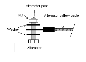 Image 7.
- Take the piece of fuel/emission line and cut it length-wise (opening to opening). Slip it over the cable and make sure a couple of centimeters extend beyond the end of the alternator post. Cut a small notch in it so it will make somewhat of a seal around the post. Secure the insulator to the cable by wrapping each end with a nylon wire tie. See Image 8 for clarification.
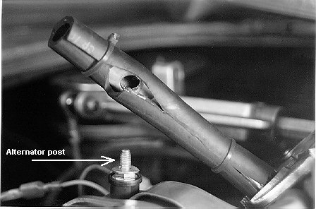 Image 8.
- Remember removing that pig tail from the back of the alternator? Well, it's time to get it connected. There are two wires coming from it. On the back of the alternator you will see a little sticker that shows what connection goes to what wire. The Ign. wire will go to the positive terminal on the coil and the other wire will go to the idiot light.
- Crimp a female spade connector on the wire that is supposed to go to the ignition (for my alternator this was the green wire). Attach the wire to the positive male spade terminal on the coil. It's identified by the number 15 next to the terminal and sometimes will also show a '+'. Generally it is the terminal that has the most wires attached to it.
- Take the other wire and crimp a male spade connector to it (this way should you have both wires disconnected you won't confuse yourself on where they should be reconnected). Crimp a female spade connector to the green wire that was disconnected from the generator. Now connect the two wires together.
- You're done! All that needs to be completed is fine tuning the seating of the belt. Reattach the ground cable to the battery and clean up the area a little bit so nothing will fall into your engine as you need to have the engine running for part of the adjustment.
- Start the engine. If you hear a loud squealing noise it means the belt isn't positioned on the alternator pulley properly. Turn off the engine because if you let it continue the pulley will become very hot within a couple of seconds!
- Chances are good that you may need to move the alternator forward (towards the flywheel) or it needs to be straightened (the pulley and belt are meeting at a slight angle and not perfectly parallel). Belt dressing will not help the problem so don't use it.
- Loosen the nuts on the hold down strap just a little bit. You want to be able to move the alternator just a very little bit at a time. This can be done by tapping the mounting flanges that extend from the alternator. Just make the adjustment you think you need, tighten the hold down strap and then start the engine up and listen for squealing. If the squealing stops then everything is proper and you are completely done!
- Optionally, you can start up the car and if it's squealing you can make your adjustments while the engine is running. This is what I do. You do need to work quickly so the pulley (and thus the alternator) doesn't become too hot but it allows you to notice what adjustment is working and which one is making it worse (similar to adjusting the timing while the engine is running). Since the engine is running you must be extremely careful -- this optional adjustment procedure is very dangerous and is not recommended for those who aren't experienced mechanics (professional or amateur)!
- You can now clean up your mess and enjoy more power! Happy motoring!!
 The final result!
Alternator Specifications and Additional Notes
Rated voltage (volts/amps) 12/40
Fixing torque of pulley
lock nut (kg-m) 5.95 ~ 8.05
Internal fan
Internal voltage regulator
Maximum current output is 40 amps (alternator rpm unknown)
The rotation ratio between the crank pulley and the alternator pulley is around 3.2:1 (maybe a little more). This means for a stock engine idling at 800-900 rpm the alternator will be able to provide an output current whereas the generator wasn't.
I installed the alternator on my 2003cc, 123hp engine and put it through a testing period of over two months of daily driving during the summer. At the time of this writing I am still using the alternator and have had no problems. I found that it is sometimes possible to throw the belt if the engine is turning 5500 rpm or more (oops, there's the red idiot light) -- luckily for us Type III owners we still get engine cooling if the belt is thrown. Unfortunately there isn't a good way to adjust the belt tension. A belt tensioner would be the perfect solution but I'm afraid that would have to be a machined item and isn't something most amateur mechanics can make. I thought putting additional support tabs may help but they really didn't -- there just isn't enough space under the deck lid. It would be nice if the alternator pulley could be replaced with one similar to the stock generator pulley.
--Updated 11Dec2003-
The previous place I got the alternator from was lying to me. After working with another shop I found out that the alternator part number is 100211-1680 NipponDenso. It's a 12v/40a alternator and the shop that sells them nickname it the "teeny-weeny". As of the given date the alternator can be purchased for about $135 at the below address:
Faulkner Auto Electric
1831 NW 28th Ave.
Portland, OR 97210
1-800-547-0361
Locally: 503-227-3567

Some facts about alternators:
Produces a charge at a lower rpm than a generator (great for those who have more than just stock accessories)
Lighter than a generator of similar output
The voltage regulator doesn't need a cutout relay
Can produce a charge in either direction of rotation (which is what the Type I gen-to-alt conversions rely upon)
Have a higher rotational speed than a generator (something to think about in a high rpm engine)
Reduced maintenance and longer life (hey, who doesn't want this?)
Disclaimer: This document and the author make no warranty of any kind, expressed or implied, with regard to this conversion process and shall not be liable in any event for incidental or consequential damages in connection with, or arising out of, the furnishing or use of this document.
In the spirit of the People's Car this document may be freely distributed and stored, either mechanically or electronically. However, it is requested that this document remain whole and complete. Under no circumstances may this document be used, in part or in whole, as a medium of trade or barter or be sold for currency without the sole written authorization of the author (that'd be me).
Please send any suggestions or comments to: air_cooled_nut@pobox.com
-- End of Document --