 Last additions Last additions |
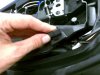
498 viewsThe resistor mounts fit in the groove of the rear rubber seat rests.Aug 02, 2014
|
|
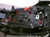
467 views"Tool tray" needs to be removed for tucking the wires in on the right side. There are six of the 4mm fasteners holding it down.Aug 02, 2014
|
|
464 viewsMy test bracket front an center proved the load resistor worked in keeping the right LED turn signal from flashing fast when engine RPM went above 3000. JST 2-prong electrical terminals and 50W, 6-ohm resistors (one per bulb).Aug 02, 2014
|
|
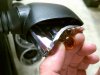
486 viewsGrasp the original bulb to gently pull the reflector straight out. I show this angled so the inside end can be seen. Gently push the bulb in just a little bit and then rotate it to remove it. Mine were in there quite snug! The LED unit goes in the same way as the bulb. Put everything back together. Done!Mar 22, 2014
|
|
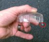
463 viewsThe red circled part shows why the lens needs to be angled out when removing it. That hook helps hold the lens in to the housing. The end opposite the hook is where the screw goes.Mar 22, 2014
|
|
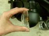
457 viewsPivot the outside of the clear lens a little and then gently pull the lens away from the housing.Mar 22, 2014
|
|
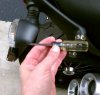
500 viewsUse a #1 Phillips screwdriver to remove the clear lens retaining screw.Mar 22, 2014
|
|
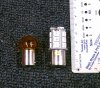
467 viewsSize comparison of the incandescent (left) bulb vs. the LED unit (right). Though the LED unit is taller it will still fit inside the signal housing with room to spare.Mar 22, 2014
|
|

With film applied.479 viewsLow beam (regular OEM bulb) and running light.Mar 15, 2014
|
|
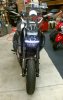
With film applied.478 viewsRunning light on.Mar 15, 2014
|
|
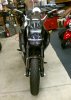
With film applied.470 viewsHeadlight and running light off.Mar 15, 2014
|
|
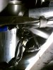
417 viewsAdd a new zip-tie to secure the headlight cables snugly, NOT TIGHTLY. Now the headlight can be mounted to the two lower anti-vibration mounts and the acorn nuts snugged. Done!Mar 15, 2014
|
|
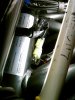
508 views3-pin connecter goes on next. Notice the positioning.Mar 15, 2014
|
|
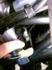
510 viewsPut the electrical connectors back together. They only go on one way so it's pretty much idiot-resistant. The 2-pin goes on first. Notice the positioning.Mar 15, 2014
|
|
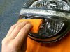
518 viewsThe improved squeegee in action, applying the bottom tint first.Mar 15, 2014
|
|
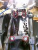
540 viewsMounting points.Mar 15, 2014
|
|

Side view, both lights covered490 viewsTop and bottom lights covered in lightest tint, LED not covered.Mar 15, 2014
|
|

517 viewsTo reduce scratches from the squeegee, wrap it in a semi-thick cloth. This is mine from a previous film application and is what I used after I noticed small scratches appearing on the film when I first started using the supplied one.Mar 15, 2014
|
|

Side view, half and half493 viewsLower half with lightest tint applied, LED and top have no film on them.Mar 15, 2014
|
|

Front view, both lights covered524 viewsTop and bottom tinted, LED running light not tinted.Mar 15, 2014
|
|
| 3332 files on 167 page(s) |
 |
16 | |
|





