 Last additions - Zoom-zoom Last additions - Zoom-zoom |
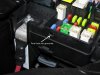
499 viewsNext, I used a 15/64" (almost 6mm which would work fine) and hand drilled the hole for the grommet (yes, I twisted it with my bare fingers). I wanted to make sure I drilled straight and using a hand-held drill would've caused the hole to be at a slight angle due to the head light housing interfering with the drill chuck.Apr 13, 2012
|
|
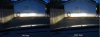
Fogs comparison with low beams on520 viewsLeft picture is with the fogs off -- Right picture is with the fogs on.Apr 03, 2012
|
|
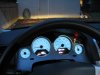
515 viewsView from the driver's seat with the fogs on. Notice the green "fog lights on" indicator to the right of the speedometer and below the red "fasten seat belt" indicator. I just finished adjusting the fog lights. The top of the light you see on the building wall is 14". If I went by the instructions it would've been 13" but I wanted just a little more distance.Apr 03, 2012
|
|

DRL LED stealing the spotlight from the turn signal.484 viewsMy current issue is the super bright DRL LEDs washing out the amber turn signal LEDs as shown in this video. Also on YouTube at http://www.youtube.com/watch?v=00wxGYhHd0k&list=UUhzs41pIUb_YugBfXOWUwvw&index=1&feature=plcpApr 01, 2012
|
|
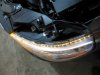
487 viewsTop view of LEDs firing.Apr 01, 2012
|
|
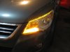
514 viewsTa-da!Apr 01, 2012
|
|
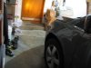
457 viewsNot great but you can see the amber of the LED turn signal as I'm standing by the rear edge of the door, about 1' away.Apr 01, 2012
|
|
Day example.480 viewsDay time demo. Also on YouTube.com at http://www.youtube.com/watch?v=Sr75SJdNsJQ&feature=relmfuApr 01, 2012
|
|
Night example.541 viewsNight time example of turn signals. Also on YouTube.com at http://www.youtube.com/watch?v=uAUECRUXoQo&list=UUhzs41pIUb_YugBfXOWUwvw&index=3&feature=plcpApr 01, 2012
|
|
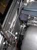
494 viewsRight side ground...had to use a 10mm box wrench (spanner).Apr 01, 2012
|
|
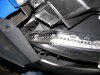
472 viewsShowing the path of the LED array as it goes down on the front part of the head light. That blue thing is simply a nylon auto trim tool I had laying nearby that I used to hold the fascia away from the head light so I could work with both hands. Now just apply power from the turn signal tap!Apr 01, 2012
|
|
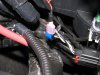
482 viewsShowing how the make connector fits on the tap-in. For the LED wires use RED connectors! I use a professional crimper to give me consistent, quality crimps. Because the LED wire was so small I strip away about 1/2" of the insulation and then fold the wire back on itself, then insert it into the connector. This allows more material (wire) to fill the space and make a more solid connection & crimp. The black 'goo' is dried liquid electrical tape. I also use electrical tape on the connector and wire to help protect the connector from collecting water.Apr 01, 2012
|
|
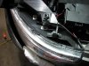
Applying the LED array to the head light.519 viewsI started from the top (right side of picture) and carefully removed the LED backing tape as I move towards the front of the head light. Just eye-balled the application but kept it more towards the inside of the light (engine side). This allows more light to be spread out onto the head light lens and disperse the light. I put a rubber tube around the wires to protect them from chaffing against the metal. Be sure to clean the lens well! I used rubbing alcohol and a clean rag.Apr 01, 2012
|
|
Getting the power ready for the turn signal LED array.501 viewsUse a BLUE wire tap-in like what I show. The ones that are RED are for smaller wire sizes and the YELLOW ones are for larger wires. I prefer these because when you insert the insulated male connector it makes a positive fit and keeps the tap locked on to the wire. -- Left side: Tap into the white wire with the GREEN stripe. -- Right side: Tap into the white wire with the BROWN stripe. -- FYI for both lights: The black wire [on the outside] is ground, the middle wire is the parking light and the other outside wire is the turn signal.Apr 01, 2012
|
|
486 viewsThe ground lug I used on the left side. Use a ring connector for the grounds. This insures the nut will still make a connection even if the nut gets loosened.Apr 01, 2012
|
|
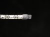
LED dual-element array (alternating white and amber LEDs).475 viewsCut the other end to the desired length or to simply remove the other wires. Use some heat-shrink at the end to seal it from the elements. I left a little over-hang and then bent the heat-shrink back on itself, then gently clamped with some needle-nose pliers.Apr 01, 2012
|
|
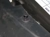
450 views...to release it from the split shaft below, making it easy to remove the entire pin assembly without breaking it.Apr 01, 2012
|
|
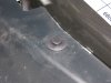
450 viewsPlastic pin used to hold the front fascia. Pry the head up...Apr 01, 2012
|
|
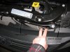
Left side shown. Right is just like the left side.462 viewsAfter removing the bumper skin fasteners remove the 10mm bolt and pin retainer. Do this for both sides (remove all fasteners). This will allow the front fascia and bumper skin to be pulled back enough to get to the head lights. The bumper is still attached to the vehicle by lower fasteners but for this situation it doesn't need to be fully removed.Apr 01, 2012
|
|
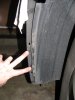
472 viewsRemove the two screws that attach the wheel well splash guard to the front bumper skin (left side shown).Apr 01, 2012
|
|
| 1529 files on 77 page(s) |
 |
15 | |
|





