 Last additions - Zoom-zoom Last additions - Zoom-zoom |

High/low beam switch454 viewsThe male part of the sliding switch for the high/low beam switch.Jan 17, 2011
|
|
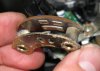
451 viewsThe female part of the sliding switch for the high/low beam switch. The long pad is the common power and the right pad is low beam, the left pad is high beam (as pictured here).Jan 17, 2011
|
|
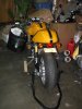
430 viewsNotes: The instructions say to clean the area with brake cleaner and scuff the area. Because I'm using the TankSlapper to protect my tank I didn't do either but I did clean the area on the TankSlapper well.Jan 01, 2011
|
|
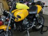
443 viewsHow it looks on the bike. Not as pretty as I had hoped but, man, does it work!Jan 01, 2011
|
|
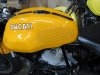
451 viewsHere's the StompGrip on the tank. The adhesive backing is 3M and it is sticky! So get everything lined up, triple checked, then peel the backing off. Place the StompGrip inbetween the marks and get it right the first time because the stuff is STICKY!Jan 01, 2011
|
|
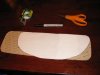
412 viewsPut the pattern on the back side of the StompGrip and trace the outline with a permanent pen. Then simply cut it with scissors. Following the instructions that come with the kit, make sure you have round corners.Jan 01, 2011
|
|
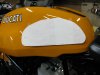
433 viewsCut the paper so you have a pattern. Tape it back to the tank, using the marks you placed earlier to property align it. Rub out the marks and put new ones down about 1/4" out. This will help when applying the StompGrip.Jan 01, 2011
|
|
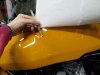
403 viewsUsing a grease pencil to mark the tank where your outline is. This is to help place the pattern later.Jan 01, 2011
|
|
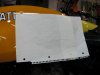
382 viewsTape some paper to the tank, sit on the bike, grip the tank, and trace around your legs.Jan 01, 2011
|
|
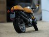
474 viewsDec 20, 2010
|
|
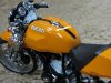
438 viewsDec 20, 2010
|
|
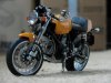
443 viewsDec 20, 2010
|
|
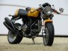
459 viewsDec 20, 2010
|
|
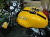
Mini Me458 viewsThe model on the actual.Dec 20, 2010
|
|
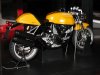
452 viewsThe rear suspension is twist-tied to the exhaust. Delicate procedure to remove it. I didn't see its purpose. The rear stand is 100% functional.Dec 20, 2010
|
|
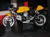
461 viewsLeft side. The front wheel stand and center body cradle can both be removed, as well as the gray twist-tie holding the bike down.Dec 20, 2010
|
|

423 viewsBottom of the display box.Dec 20, 2010
|
|
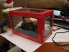
463 viewsHow it looks in the display box before unpacking.Dec 20, 2010
|
|
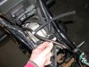
448 viewsHere's the hoses merged together. Cut the bleed hose about 6" down and insert the horizontal part of the tee. Connect the 8" hose. Done!Dec 18, 2010
|
|

458 viewsWhat you need: A barbed "T"-fitting that's 1/4" at each end. I used an 8" piece of fuel line instead of cutting the original drainage hose.Dec 18, 2010
|
|
| 1529 files on 77 page(s) |
 |
23 | |
|





