 Most viewed |
571 viewsAfter.
|
|

569 views
|
|
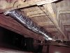
569 viewsLooking forward at the center section. I clipped off the stock duct zip-ties, wrapped the duct, and then zip-tied the duct back to the mounting points.
|
|

568 viewsHey little girl, how ya doin'?
|
|

Day 2: Saturday568 viewsThe next day the "prom-queens" wash their rides at a children's car wash. The kids made out pretty good; we paid them $3 and we washed our own cars while they watched and asked a bunch of questions. Funny looking cars with their engine in the back can create quite a few.
|
|

568 viewsThe 3-pin connector apart. Next up is the 2-pin connector. After that the headlight can come completely off the bike. This is done by pushing the assembly up in the same direction as the fork tubes until the bracket comes off the upper pegs. Pull it forward a little to clear the pegs then downward (if a Strada windshield is in the way) and forward to clear the bike.
|
|

567 views
|
|
566 viewsFog wiring harness, right side, zip-tie location.
|
|
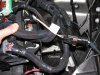
565 viewsAll wired up, fog harness plugged in & grounded, and the fuse box ready to be re-installed. I used a stock grounding point under the module per the Routan instructions. The Chrysler instructions show the ground attached to the negative battery cable.
|
|
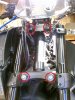
565 viewsMounting points.
|
|

565 viewsBefore, low-beam.
|
|

564 viewsDarned squirrels partied last night and didn't clean up!
|
|
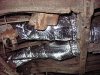
563 viewsSame duct, just took the picture from the left side of the Bus. Wrapping this duct is likely the most difficult of all the ducts so go slow and think. I know the pictures aren't a huge help but they give an idea. I'm sure there's more than one way to insulate this loop.
|
|
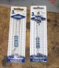
563 viewsHere are the resistors...beefy! They are 3 watts each. If you use a smaller wattage resistor they will get hot!! These will get warm but not hot. One is 1-ohm and the other 16-ohms. You wire them in series so you get a total of 17-ohms resistance. So you can use any combination of resistors you want, just shoot for 17-ohms. This puts my gas gauge needle right on the first white mark (left side) of the red Reserve section but the needle will go a little past the Full mark when the tank is topped up. Add more resistance to have the needle move down more but I'm guessing that a total of 20-ohms would be the max to use.
|
|

562 viewsFresh from the oven ;-)
|
|

562 views
|
|
561 views
|
|
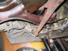
561 viewsNotice e-brake cable is above engine bar. Remember this when installing engine.
|
|
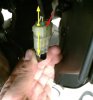
561 viewsTo separate the two electrical connectors simply lift the tab (red arrow) and gently pull the male connector (what I'm holding) from the female (top) (yellow arrows).
|
|
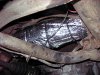
560 viewsThe right side fully wrapped with no problem. By the way, I'd recommend disconnecting the battery when working on the Y-section and back (like this part) as the insulation can conduct electricity and there is the starter chillin' out there, with it's +12v constant supply just waiting for some action ;-)
|
|
| 3332 files on 167 page(s) |
 |
20 | |
|





