 Most viewed - Ducati Most viewed - Ducati |
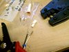
554 viewsThe JST electrical connectors/terminals are tiny, delicate, and not easy to get inserted into the plugs. The crimpers on the right are just for these pins and were just over $40, which is CHEAP because the good ones go for over $400.
|
|
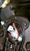
554 viewsI tucked the headlight connector into the middle left side of the headlight, below the white headlight adjustment mechanism. If you adjusted the headlight vertical adjustment earlier this is when you will want to return it back to its original position, rotating it clockwise.
|
|
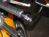
551 viewsTo remove, simply loosen the bolt a few turns and pull the whole assembly out.
|
|
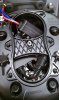
551 viewsI didn't get pictures of all the steps after this one because it's a bit fiddly. This shows roughly how you want to start the process of rotating the ballast anti-clockwise and move it a little left of center under that hourglass brace (center of headlight bucket). The electrical cables coming from the ballast will be pointing to the right side of the headlight bucket and the power plug will be up and next to the ignitor when done.
|
|

549 viewsBefore, high-beam.
|
|

549 viewsAfter, low-beam.
|
|
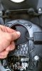
546 viewsRotating ballast clockwise to get it in there. The single electrical connector, or plug, goes down the right side of the headlight housing and then towards the high-beam bulb holder.
|
|

545 viewsTwo terminal connector comes apart just like the three terminal connector.
|
|
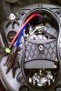
544 viewsThis is how it should look when done. The hard part of this install has been completed!
|
|
543 views
|
|
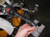
543 viewsSlide/peel the stock grip off.
|
|
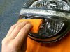
542 viewsThe improved squeegee in action, applying the bottom tint first.
|
|

541 viewsTo reduce scratches from the squeegee, wrap it in a semi-thick cloth. This is mine from a previous film application and is what I used after I noticed small scratches appearing on the film when I first started using the supplied one.
|
|

540 viewsComes with everything you see here, including a knife for trimming excess film off and a very nice water mister. Follow the instructions! I did use the sharp knife to trim the mounting tabs off (they're only used for positioning the film). I placed the film closest to the inside edge of the lens (near the center of the headlight) to get the best coverage.
|
|

Front view, both lights covered539 viewsTop and bottom tinted, LED running light not tinted.
|
|

Side view, both lights covered539 viewsTop and bottom lights covered in lightest tint, LED not covered.
|
|

539 viewsAfter, low-beam.
|
|

539 viewsBefore, high-beam.
|
|
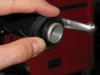
535 viewsThe right grip is held on by a ridge on both ends of the throttle so peel the grip off them.
|
|
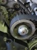
535 viewsLine up the pulley markings with those on the engine case. I used a white grease pencil (china marker) to mark the points on both the case and pulleys for faster visual confirmation. You can see here I drew a line all of the way across the horizontal belt and center pulley as a precaution. I marked the replacement (new) horizontal belt the same way as the vertical belt explained here.
|
|
| 428 files on 22 page(s) |
 |
11 | |
|





