 Most viewed - Ducati Most viewed - Ducati |
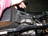
458 viewsI'm holding the hose that I'm going to merge and thus remove. The one near the bottom of the picture with the brass hose clamp is the hose that will remain and thus serve as the bleed and drainage line.
|
|

458 viewsWhat you need: A barbed "T"-fitting that's 1/4" at each end. I used an 8" piece of fuel line instead of cutting the original drainage hose.
|
|
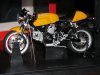
458 viewsLeft side. The front wheel stand and center body cradle can both be removed, as well as the gray twist-tie holding the bike down.
|
|
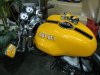
Mini Me458 viewsThe model on the actual.
|
|
458 views
|
|
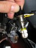
458 viewsHere's the LED replacement, ready for use.
|
|

458 viewsThe PCIII-USB and the extensions completed, ready for installation!
|
|

458 views
|
|

457 viewsRight side of the engine showing the two connectors for the front (horizontal) cylinder injector. The ORANGE wires from the PCIII go here.
|
|
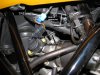
457 viewsLeft side of the engine showing the two connectors for the rear (vertical) cylinder injector. The YELLOW wires from the PCIII go here.
|
|

Detail 3457 viewsThe Ohlins shock (left) has an adjustable lower mount as seen by the blue locking nut and threads.
|
|
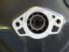
457 viewsRemove the center cover on the left side to expose the end of the crank. This is what you'll see.
|
|
455 viewsOther side of the bar showing the locating pin and hole.
|
|
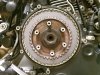
455 viewsClutch pack in!
|
|
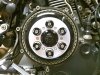
455 viewsVented EVR pressure plate mounted and springs/spring caps installed. In a star pattern, screw the bolts all the way down until they stop, THEN you continue the star pattern to torque them down. I placed the EVR logo at about the 4 o'clock position and then torqued the bolts, allowing the cap to rotate and thus line up neatly. It did take several tries.
|
|
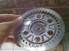
455 viewsSame thing, just a view from the back side.
|
|
454 views
|
|

Detail 2452 viewsThe Ohlins shock has more threads for more adjust-ability, likely for the range of springs it can accommodate.
|
|

451 viewsThese are the inner-most plates. Only slightly less wear than the fronts.
|
|
451 viewsAdd a new zip-tie to secure the headlight cables snugly, NOT TIGHTLY. Now the headlight can be mounted to the two lower anti-vibration mounts and the acorn nuts snugged. Done!
|
|
| 428 files on 22 page(s) |
 |
18 | |
|





