 Most viewed - Zoom-zoom Most viewed - Zoom-zoom |
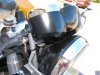
689 viewsThe gauges ever so slightly touch the headlight bucket.
|
|
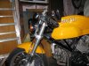
...after (hi-rise clip-ons).685 views
|
|
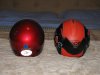
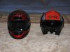
Back side683 viewsChin bar in rear position.
|
|
683 views
|
|

Mounting measurements678 viewsAll measurements are from the inside boundaries. Final measurements may slightly differ (~1/8") after bolts are tightened. This won't affect operation.
Drilling requires a 1/2" drill bit for metal. All of the holes in the vise parts are on the large side so there is a little bit of room for small tweaks in mounting positioning.
|
|
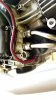
677 viewsClose-up of the OEM cable (red line) as it wraps around the front of the clutch and then to the starter post on the starter.
|
|
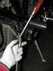
676 viewsWith patience and a little wiggling, use the screwdriver to help coax the coupling nut into the bracket.
|
|
673 viewsSC-1000 to tower, requesting fly-by!
|
|
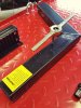
672 viewsI chased the clamp bolt holes with a tap to expose the bare metal. I opted to not use the supplied lock washers because I don't like the idea of them digging into the paint and exposing the metal to air and moisture (rust). So ALL fasteners have blue Loctite on them to hold them in place. I used a flat washer under every bolt head and under every nut.
|
|

Before (stock clip-ons)...666 views
|
|
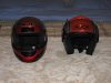
662 viewsChin bar in back position.
|
|
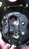
660 viewsRemove the headlight and place on a thick towel. The low-beam is at the top of the headlight, which is the top of this picture. This shows the back removed and the bulb area exposed -- there are 7 screws that hold the back on. The greyish-silver bolt at the 11 o'clock position on the outside edge is the headlight vertical adjustment. To get more operating space inside the housing I rotated mine anti-clockwise 6 turns. Make sure you mark the bolt with a spot on the housing so you know where to return it when everything is all installed.
|
|
659 views
|
|

659 views...and screw the cap back on. This will help keep the DOT-4 fluid from flowing out when you remove the banjo fitting from the stock unit.
|
|

Skully grips by Driven652 viewsBefore. Stock grips.
|
|

646 viewsOther angle.
|
|

645 viewsThe four bolts are removed and the cover is on the ground (it's resting on a foam Frisbee). Notice that the bolts are different lengths so make sure you put them back in the same holes. You can also see the clutch dust in the cover and on the exhaust pipe.
|
|
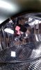
633 viewsLooking that the bulb reflector/cover from the front of the headlight. Use the eraser end of a pencil through the opening to GENTLY push the reflector forward -- towards the headlight glass -- so the HID bulb won't touch it. Every panel on the reflector is EASILY bent so take your time and GO SLOWLY! You want to push from the center of the reflector and just a couple millimeters. Test fit the HID bulb and gently wiggle it around, feeling that the tip doesn't touch the reflector.
|
|
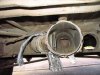
631 viewsLooking forward, this is the point where the main heater duct connects to the forward 'Y' where some heat can be diverted to the interior floor vent that is between the driver/passenger seats that points into the center of the Bus. Here the flap is closed so all heated air goes to the front of the Bus.
|
|
631 viewsSlide the bracket back down (shown here where it comes from), pop the breather back in the loop, then bolt the bracket back onto the engine.
|
|
| 1529 files on 77 page(s) |
 |
13 | |
|





