 Most viewed - Zoom-zoom Most viewed - Zoom-zoom |
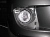
605 viewsRight fog light installed, front view. Note that adjusting screw is always at the top.
|
|

605 viewsBottom covered, LED and top uncovered.
|
|
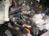
602 viewsEngine lowered and pulled back a little so left axle can be maneuvered to the top of the starter.
|
|
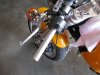
602 viewsRaw handle bar. Removing the left side is easy. Squirt some Windex(R) under the grip to help loosen its "grip" and make it easier to slip off.
|
|
601 viewsI just HAD to take her for a buzz around the block and since I'm used to my Goldwing I hit the throttle a tad too much and lifted the front...
|
|
600 viewsWhat do you do with the left-over stock grips? You could use 'em for handle holders.
|
|
600 views
|
|

599 viewsBoth top and bottom covered, LED uncovered. I know the bottom looks blueish but the film is the same color on top and bottom.
|
|
598 viewsNapoleon mirror removed.
|
|
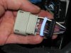
598 viewsSeparate the bottom plug (black) and the seal (light blue) within. You'll need to unwrap the black electrical tape on the wiring and throw it away. This will give you the needed slack in the wiring.
|
|

597 viewsDue to the accessory plug on the left side the left bracket couldn't be a mirror image of the right side. I ultimately had to weld another piece of metal to bridge the original pieces, moving the resistor mounting plate further inboard and to the rear.
|
|
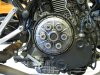
594 viewsThe original OEM clutch.
|
|
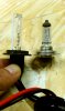
594 viewsHID on the left, OEM H7 on the right. Notice that the HID bulb is taller.
|
|
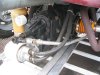
Formula Vee tail shifter592 views
|
|

592 viewsRemove these four bolts (4mm Allen) to free the headlight from the headlight fairing.
|
|
591 viewsAnother view.
|
|
587 viewsBefore, low-beam. FYI: The ground in these before/after pictures is our asphalt driveway.
|
|

586 viewsHere's the replacement cover, a Rizoma unit. All you need is a 5mm Allen wrench. Not pictured, but still needed, is some blue Loctite.
|
|

585 viewsShows how the top and bottom parts of the headlight fairing join.
|
|
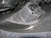
584 viewsBack side of the right fog light housing.
|
|
| 1529 files on 77 page(s) |
 |
15 | |
|





