 Most viewed - Zoom-zoom Most viewed - Zoom-zoom |
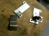
521 viewsLeft side are the 'raw' bits that make up the mounts. On the right is the completed right mount.
|
|
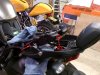
521 viewsRemoving the pillion backrest and grab handles is very easy. There are only three, 6mm bolts. One under the seat on each side (red arrow) and the other one is below the back rest mount, center-line of the seat. Be careful when lowering it due to all the wiring. I would also recommend covering the rear fender to protect both pieces from being scratched.
|
|
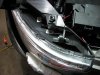
Applying the LED array to the head light.520 viewsI started from the top (right side of picture) and carefully removed the LED backing tape as I move towards the front of the head light. Just eye-balled the application but kept it more towards the inside of the light (engine side). This allows more light to be spread out onto the head light lens and disperse the light. I put a rubber tube around the wires to protect them from chaffing against the metal. Be sure to clean the lens well! I used rubbing alcohol and a clean rag.
|
|
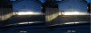
Fogs comparison with low beams on520 viewsLeft picture is with the fogs off -- Right picture is with the fogs on.
|
|
520 viewsInstalled and ready to ride!
|
|

519 viewsOkay, learn from me. The grips come in two internal diameters. The smaller diameter goes on the left while the larger one goes on the right (throttle) side.
|
|
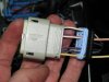
519 viewsHow it looks all wired up.
|
|
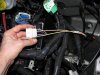
519 viewsHow it looks with the plug put all back together.
|
|
518 views
|
|
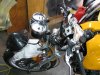
518 viewsIn order to remove the upper triple-tree the headlight needs to be removed and then the U-shaped ladder part that the headlight attaches to is then removed. Remove the two nuts at the bottom of the ladder then lift it up. Also, disconnect the headlight connector and put the headlight out of the way.
|
|

518 viewsI originally tapped the existing mounting holes in the resistors with 4M x .7 threads but I decided to add Nyloc nuts to insure nothing came loose. All fasteners I used are stainless steel.
|
|
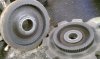
518 viewsInside of forward gear and planetary gear mating teeth.
|
|

517 viewsI used the top of the hole in the bolt where the Allen wrench entered.
|
|
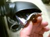
516 viewsGrasp the original bulb to gently pull the reflector straight out. I show this angled so the inside end can be seen. Gently push the bulb in just a little bit and then rotate it to remove it. Mine were in there quite snug! The LED unit goes in the same way as the bulb. Put everything back together. Done!
|
|
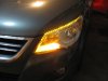
515 viewsTa-da!
|
|
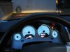
515 viewsView from the driver's seat with the fogs on. Notice the green "fog lights on" indicator to the right of the speedometer and below the red "fasten seat belt" indicator. I just finished adjusting the fog lights. The top of the light you see on the building wall is 14". If I went by the instructions it would've been 13" but I wanted just a little more distance.
|
|
514 views
|
|
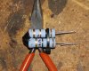
514 viewsI used a small zip-tie to keep the resistors together while working on them. Not critical to have but makes the pack more sturdy and easier to handle. You can also see that I bent the wires back on themselves, essentially making them thicker. This allowed me to crimp spade connectors to them...
|
|
514 views
|
|
514 viewsRemoving the spacer.
|
|
| 1529 files on 77 page(s) |
 |
22 | |
|





