 Most viewed - Zoom-zoom Most viewed - Zoom-zoom |
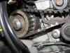
501 viewsFor the inner belt that runs the vertical (rear) cylinder I made my own mark on the belt and pulley at about the center spot.
|
|
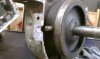
501 viewsThe pin is missing. Looks melted...??? Without this pin set in the case halves the planetary ring rotates and doesn't allow the forward gear to rotate properly.
|
|
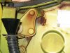
500 viewsWhen the engine is out you can weld/replace the rear trunk pivots. Oh what joy.
|
|
499 views
|
|
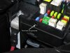
499 viewsNext, I used a 15/64" (almost 6mm which would work fine) and hand drilled the hole for the grommet (yes, I twisted it with my bare fingers). I wanted to make sure I drilled straight and using a hand-held drill would've caused the hole to be at a slight angle due to the head light housing interfering with the drill chuck.
|
|
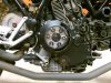
499 viewsMounted and behind my Rizoma vented clutch cover.
|
|

With film applied.499 viewsLow beam (regular OEM bulb) and running light.
|
|
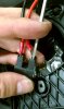
499 viewsThe spade connectors snap in. If they are difficult to get out (at a later date, say, when replacing the bulb) you may want to use a thin, flat-bladed screwdriver to push the spade away from the female contact as shown.
|
|
498 views
|
|

497 viewsI used a 5/8" socket to support the bearing so I could drive out the push rod.
|
|
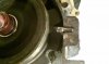
497 viewsRepaired pin cut, ground further, and beveled. Fits in the hole nicely! Remember, the planetary ring will move side-to-side so make sure the pin isn't butted against the end of the hole. Allow for the movement.
|
|
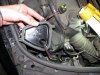
496 viewsCable passed through hole, ready for the gasket.
|
|

496 viewsThe "OUT" port is on the right side of the tank and this is where the fuel is outputted to the fuel injectors. The "IN" port is where the fuel is pushed back into the tank/pump. At the end of the IN port, inside the tank, is the pressure regulator.
|
|
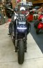
With film applied.496 viewsRunning light on.
|
|
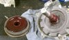
496 viewsBearing grease (red) applied on the planetary teeth for mating to the rearward gear. I followed the instructions for the "new" teeth so I hope this is okay for the "old" teeth. I think it should be.
|
|
495 views
|
|

495 viewsHere's what they look like. A simple and effective design. Here's where you can get 'em:
http://www.bhpbikeparts.co.uk/content/products/
|
|
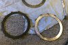
495 viewsThis is the outer-most friction plate and driven plate. The average thickness of the friction plates was ~2.8mm. They should be replaced if they are less than 3.2mm!
|
|
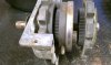
495 viewsCloser-up. Exploded view. Notice pin is short...it came to us broken.
|
|
494 views
|
|
| 1529 files on 77 page(s) |
 |
25 | |
|





