 Most viewed - Zoom-zoom Most viewed - Zoom-zoom |
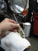
494 viewsUse a Phillips screwdriver to remove the retaining screw at the bottom of the headlamp. No need to completely remove the screw, just until it becomes loose & wobbly.
|
|
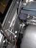
494 viewsRight side ground...had to use a 10mm box wrench (spanner).
|
|

494 viewsThe PCIII protected inside some bubble-wrap and under the seat.
|
|
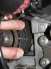
494 viewsWith the horizontal (front) cylinder belt removed I lined up my replacement belt for the vertical cylinder and marked it.
|
|
493 views
|
|
493 views
|
|

493 viewsA quick video tour of the installed harness. For easier viewing please go to http://www.youtube.com/watch?v=h8ePhGSbxso
|
|

493 viewsThe right side mounted. Easy. It hides under the seat base and is away from the seat edge, thus touching nothing.
|
|
493 viewsReference picture.
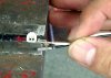
22GA wire. How the terminals look and are positioned for insertion (crimps up) into the plastic housing.
|
|
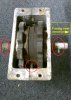
Reference: Front gear box493 viewsPlanetary pin on left side of box (bottom of picture), drive shaft with roll pin is on the right side of the picture.
|
|
492 views
|
|
492 views
|
|
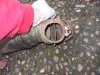
492 viewsHere the flapper is opened all of the way so all of the heated air goes into the Bus interior. This system is used by all the Types of engines (Type I/II, III, & IV).
|
|
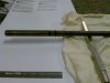
492 viewsWhile I was "in there" I decided to change out the O-rings at the other end of the push rod.
|
|

491 viewsHow it looks using a vice. The push rod is free to move as the socket is resting on the vice clamps.
|
|
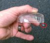
491 viewsThe red circled part shows why the lens needs to be angled out when removing it. That hook helps hold the lens in to the housing. The end opposite the hook is where the screw goes.
|
|
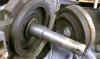
491 viewsInside of rearward gear and planetary gear mating teeth.
|
|
490 views
|
|
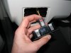
490 views...and now it's in the 'locked' position. I noticed many of the electrical connectors had some sort of lock on them. If you see a red tab/button then that's a connector lock.
|
|
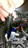
490 viewsTo make it a little easier getting both of the HID wires into the small space I put a single loop in the wire, as shown. Then stuff it in there with the red wire.
|
|
| 1529 files on 77 page(s) |
 |
26 | |
|





