 Most viewed - Zoom-zoom Most viewed - Zoom-zoom |

Turn signal switch490 viewsAll apart. Use white lithium on the left part of the switch, where the ball bearing rubs against the left wall. Use dielectric grease everywhere else.
|
|
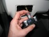
490 views...and now it's in the 'locked' position. I noticed many of the electrical connectors had some sort of lock on them. If you see a red tab/button then that's a connector lock.
|
|
489 views
|
|
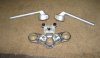
489 viewsJust a picture of the stock '06 clip-ons and the bottom side of the upper triple tree.
|
|
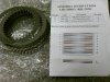
489 viewsThe new clutch pack and stacking instructions. No idea what the bottom image is for, I just used the top part.
|
|
489 viewsMy test bracket front an center proved the load resistor worked in keeping the right LED turn signal from flashing fast when engine RPM went above 3000. JST 2-prong electrical terminals and 50W, 6-ohm resistors (one per bulb).
|
|
488 viewsFlap fully open, allowing some of the heated air to divert into the center of the Bus for the rear passengers.
|
|
488 viewsTop view of LEDs firing.
|
|

488 viewsThe clutch stack. See how the left edge of the friction plate teeth are worn and hammered.
|
|
488 viewsNew basket placed within. Use 4 bolts, snugged in a star pattern, to seat the basket onto the hub.
|
|
487 views
|
|
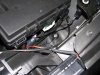
487 viewsThe ground lug I used on the left side. Use a ring connector for the grounds. This insures the nut will still make a connection even if the nut gets loosened.
|
|
486 views
|
|
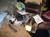
486 viewsXentec - The kit I used. Also, remove the DRL (Daytime Running Lights) relay, #173. It's located where the fuses are but a little deeper behind the dashboard -- it easily pulls straight out. Yes, you'll have to manually turn on your lights when you drive now. You can drive with the relay intact and the lights will come one (well, ours did), but the HIDs are getting a reduced voltage and may not turn on, they could even turn off while driving due to the reduced voltage feeding them. By removing the relay you insure that they get full voltage when you turn on the headlights.
|
|

...after.486 viewsThe bottom of the switch is at 36".
|
|
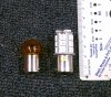
486 viewsSize comparison of the incandescent (left) bulb vs. the LED unit (right). Though the LED unit is taller it will still fit inside the signal housing with room to spare.
|
|
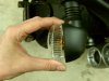
486 viewsPivot the outside of the clear lens a little and then gently pull the lens away from the housing.
|
|
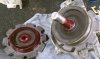
486 viewsSame thing for forward gear.
|
|

485 views
|
|
...after.485 views
|
|
| 1529 files on 77 page(s) |
 |
27 | |
|





