 Most viewed - Zoom-zoom Most viewed - Zoom-zoom |
...after.485 views
|
|

DRL LED stealing the spotlight from the turn signal.485 viewsMy current issue is the super bright DRL LEDs washing out the amber turn signal LEDs as shown in this video. Also on YouTube at http://www.youtube.com/watch?v=00wxGYhHd0k&list=UUhzs41pIUb_YugBfXOWUwvw&index=1&feature=plcp
|
|
484 views
|
|
484 viewsOther side of the right bar showing another locating hole.
|
|
483 views
|
|
483 viewsFog harness using a hook on the right side radiator fan surround.
|
|
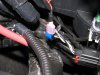
483 viewsShowing how the make connector fits on the tap-in. For the LED wires use RED connectors! I use a professional crimper to give me consistent, quality crimps. Because the LED wire was so small I strip away about 1/2" of the insulation and then fold the wire back on itself, then insert it into the connector. This allows more material (wire) to fill the space and make a more solid connection & crimp. The black 'goo' is dried liquid electrical tape. I also use electrical tape on the connector and wire to help protect the connector from collecting water.
|
|
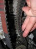
483 viewsBecause the teeth line up on the center pulley you can place the replacement belt right next to the old belt, lining up the belts tooth to tooth. No need for counting!
|
|
483 viewsAnd with mia ragazza herself.
|
|
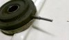
483 viewsPin welded in and ground. The gears are plastic and so after each weld you need to dip the pin into water to cool it down otherwise the plastic holding the pin will melt...as I found out. But the plastic didn't melt too badly and the original pin is still secure.
|
|
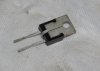
482 viewsHere's the VR. The center pin is a ground and the easiest way to ground it is to CAREFULLY bend it back onto the backside of the VR body. It will then be pressed against the gauge cluster body that is grounded. The pins are delicate and if you bend them too much they will break!
|
|
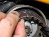
482 viewsAt the top pulley you mark the replacement belt perfectly with the mark on the old belt. You can now remove the vertical belt and quickly replace it with the new belt, followed by the horizontal belt. Adjust the belt tension and then go ride!
|
|
Day example.480 viewsDay time demo. Also on YouTube.com at http://www.youtube.com/watch?v=Sr75SJdNsJQ&feature=relmfu
|
|
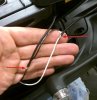
480 viewsI made a pigtail bridge, effectively just lengthening the distance between the original electrical plugs. This allows me to put the resistor into the circuit, in parallel. This tricks the ECU into thinking it's running incandescent bulbs & thus keeps it from rapidly flashing (bulb-out warning). I was successful on the right side with using blue splice/snap-lock connectors. The left side it wasn't working so I ended up soldering the resistor leads directly to the bridging wires. Perfect. In hind-sight I should've done this to the right side...oh well, some other day. Coated with liquid electrical tape & then wrapped in real tape.
|
|
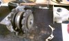
480 viewsTaken apart with the rear case fully removed.
|
|
479 views
|
|
478 views
|
|
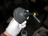
478 viewsSeat the wiring gasket as so...pretty dang obvious. How it should look.
|
|
In the raw comparison478 viewsComparison of the two bulbs. On the left is the standard incandescent and on the right is the LED unit.
|
|
476 viewsLined up.
|
|
| 1529 files on 77 page(s) |
 |
28 | |
|





