 Most viewed - Zoom-zoom Most viewed - Zoom-zoom |

469 viewsAnother shot & ready to go into the yellow 914 you see in the background :-)
|
|
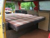
468 viewsRear seat folds out into a bed with room for two adults.
|
|
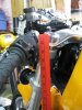
Before...468 viewsThe bottom of the switch housing is at 34".
|
|

468 viewsHarbor Freight trim tool (nylon kit, non-scratching, less than $6) used to pry the light switch out. Very easy.
|
|

468 viewsThis shows just how much the head lamps are angled on top. The left side has the LED array far back (towards the engine) whereas on the right side I wasn't as accurate and the LED array is about 3mm-5mm more forward (away from the engine). This clearly shows how the lip on the head lamp disburses the light. The left side is what I was originally looking for so I should've been more patient when installing the right side. Experience gained.
|
|
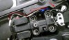
468 viewsThe pigtail length I used was 35mm and the red line shows how it's laid inside the seat pan with the resistor wires coming in an OEM hole (arrow) and spliced into it. This is all hidden by the "tool tray". I could've shortened it by a couple centimeters but it works as is.
|
|
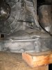
466 viewsMy rebuilt tranny still had oil in it. But tipping it on it's bell-housing would let the oil leak out the breather port. So I pushed a plug into the hole on the breather and securly zip-tied it. Worked perfectly to hold the oil in while I swapped tail covers.
|
|
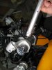
466 viewsRight side showing locating pin and hole.
|
|
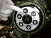
466 views...to mate with the notch in the one clutch spring post. I seriously don't think it matters but I tried to follow the workshop manual instructions as closely as I could, just in case.
|
|
465 viewsShoulder portion of belt locked in place.
|
|
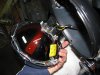
465 viewsThe headlamp exposed. Pretty darn simple in there.
|
|
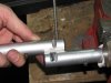
465 viewsThe top bar has the stock groove in it and the bottom one shows the extra material I had to remove, about 3/4 of the width of the original groove. Both bars required this modification. This allows the bar to be positioned "down" more so the reservoir clamps/brackets can fit on the bars. I used a hack saw to make the initial removal of material then used a rat-tail (round) file to further remove material and neaten the curves. Remember to remove just a little instead of too much! These are aluminum and it's very easy to work with.
|
|
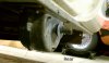
Reference shot465 viewsRear mounted gear box. On left side of trailer looking to the right side.
|
|
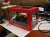
464 viewsHow it looks in the display box before unpacking.
|
|
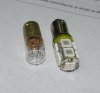
464 viewsClose-up comparison of the incandescent bulb (left) and the LED replacement (right).
|
|
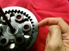
464 viewsI used the hole in the pressure plate...
|
|

463 viewsRear comparison. Notice that the wiring terminals are in a different location. Doesn't affect installation.
|
|
463 views
|
|
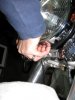
Fingernails help here.463 viewsPut your fingers between the headlamp bucket and the chrome headlamp ring and pull the bottom of the headlamp out. It only needs to travel a centimeter or two for it to be free. Unhook the top and carefully lay the headlamp on the fluffy towel you placed on the fender (that's a hint).
|
|
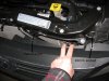
Left side shown. Right is just like the left side.463 viewsAfter removing the bumper skin fasteners remove the 10mm bolt and pin retainer. Do this for both sides (remove all fasteners). This will allow the front fascia and bumper skin to be pulled back enough to get to the head lights. The bumper is still attached to the vehicle by lower fasteners but for this situation it doesn't need to be fully removed.
|
|
| 1529 files on 77 page(s) |
 |
30 | |
|





