 Most viewed - Zoom-zoom Most viewed - Zoom-zoom |
443 views
|
|
443 views
|
|
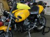
443 viewsHow it looks on the bike. Not as pretty as I had hoped but, man, does it work!
|
|
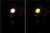
Night-time, parking lamp only443 viewsComparison of the two bulbs in the dark. On the left is the standard incandescent and on the right is the LED unit.
|
|
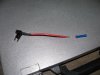
Fuse tap!443 viewsThis is how to easily and safely tap into some power without compromising the stock wiring or running a long lead through the firewall. I cut the bullet connector off so I could pass the wire through the grommet hole and so I could use one of my own spade connectors. To be on the safe side, make sure the fuse tap can handle 25A to 30A minimum. A 10A fuse tap won't work! The bottom slot is for the placing the stock fuse while the top is for the accessory and thus the red wire leading from the fuse tap.
|
|
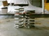
443 viewsHeight difference between the new stainless steel spring on the left and the tired steel OEM spring on the right.
|
|
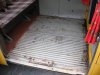
442 viewsClose-up. The black plastic plugs are for seat belt mountings. The attachment points for a 2-person or 3-person seat are there in the middle, just waiting to get used :-)
|
|
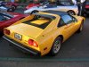
441 viewsFerrari 308.
|
|
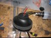
441 viewsHere's the rubber boot turned inside-out to get a better view of the inside of the gasket and the wires running through it.
|
|

441 viewsHow the wire will be placed in the connector.
|
|
440 views
|
|
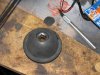
440 viewsTo hold the cover up while cutting, I used a 1/2" socket underneath. Use a very sharp Xacto blade and cut s-l-o-w-l-y and carefully.
|
|
439 views
|
|
439 viewsAlteration B.
|
|
439 views
|
|
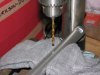
439 viewsIt seems that the locating pin on the '06 throttle clamp is 180-degrees off compared to later models. The fix was simple: Use a 5/32" drill bit and drill straight through the existing hole. Easy-peasy!
|
|

438 viewsMy girls taking it easy whilst I go drooling...
|
|

438 views
|
|

438 viewsBella makes the car look BIG.
|
|

438 viewsI will close the door, Daddy!
|
|
| 1529 files on 77 page(s) |
 |
36 | |
|





