 Most viewed - Zoom-zoom Most viewed - Zoom-zoom |

428 viewsWear on original starter.
|
|
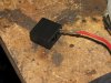
428 viewsMy kit came with holders that the wires clip into -- notice the orientation of the tang, it faces inside so it will lock in place.
|
|
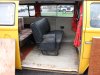
428 views2-person seat installed, yeay!!
|
|

428 viewsWhen putting the female part of the switch onto the male part, make sure the sliding contact doesn't catch on the electrical pads on the female piece. Use a scribe or small, flat screwdriver blade to hold it down as you slide the female part on.
|
|

427 views
|
|
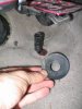
427 viewsThe round disc simply pulls off the accelerator pedal stop. Carpet can then be lifted over the stop.
|
|
427 views
|
|
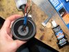
427 viewsViewing inside after applying the RTV.
|
|
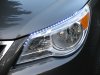
427 viewsIn the shade.
|
|
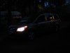
427 viewsWith low beams on. Very visible from the sides.
|
|
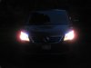
427 viewsLow beams on.
|
|
426 views
|
|
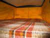
426 viewsUpper sleeping area inside pop-top has room for two adults as well!
|
|
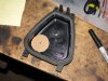
Through the hard cover426 viewsJust an FYI: I do NOT recommend this method! PITA if you have any issues. Go through the rubber cover.
Make a template that is 7/8" in diameter and trace with a permanent marker. Or put a nail or screw into the center of the circle and tap it so it leaves a dimple -- that's where you will drill. I used this location because it gave me the most slack in the wiring. The shop that does this recommended not putting the gasket in the center of the hard cover because there wouldn't be enough wiring slack.
|
|
426 viewsBottom of the display box.
|
|

426 viewsPut the plug wire on the spark plug and figure out how long you need it. This was a short wire and I had half left over. Motorcycle spark plug wires tend to be shorter than your average V8.
|
|
426 viewsThe 90-degree boot is on the wire and ready to be slid down. As per the instructions, just a spritz (very light coat) of WD-40 really helps move the boot down the wire.
|
|

426 viewsWire passed through and new connector crimped on. Fuse tap is ready to replace the M6 20A fuse. I chose this one because it's powered only when the van is on. This fuse is for the #1 ignition switched power plug and rain sensor...our van doesn't have a rain sensor so it's got power to "spare"...heeheehee.
|
|

426 viewsJust after sunset. At the time I took these pictures it was brighter out than what appears in the images. The LEDs are bright enough to the camera that it used a faster shutter speed, thus making the image look darker than it really is.
|
|

426 views
|
|
| 1529 files on 77 page(s) |
 |
39 | |
|





