 Most viewed - How-to Most viewed - How-to |
464 viewsSame thing for forward gear.
|
|
463 views
|
|
461 views
|
|
461 viewsThe ground lug I used on the left side. Use a ring connector for the grounds. This insures the nut will still make a connection even if the nut gets loosened.
|
|
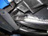
461 viewsShowing the path of the LED array as it goes down on the front part of the head light. That blue thing is simply a nylon auto trim tool I had laying nearby that I used to hold the fascia away from the head light so I could work with both hands. Now just apply power from the turn signal tap!
|
|
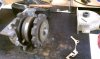
461 viewsTaken apart with the rear case fully removed.
|
|
460 views
|
|
460 views
|
|
460 views
|
|

460 viewsThis shows just how much the head lamps are angled on top. The left side has the LED array far back (towards the engine) whereas on the right side I wasn't as accurate and the LED array is about 3mm-5mm more forward (away from the engine). This clearly shows how the lip on the head lamp disburses the light. The left side is what I was originally looking for so I should've been more patient when installing the right side. Experience gained.
|
|
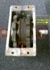
Reference: Front gear box460 viewsPlanetary pin on left side of box (bottom of picture), drive shaft with roll pin is on the right side of the picture.
|
|
459 views
|
|
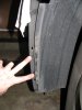
459 viewsRemove the two screws that attach the wheel well splash guard to the front bumper skin (left side shown).
|
|
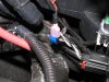
459 viewsShowing how the make connector fits on the tap-in. For the LED wires use RED connectors! I use a professional crimper to give me consistent, quality crimps. Because the LED wire was so small I strip away about 1/2" of the insulation and then fold the wire back on itself, then insert it into the connector. This allows more material (wire) to fill the space and make a more solid connection & crimp. The black 'goo' is dried liquid electrical tape. I also use electrical tape on the connector and wire to help protect the connector from collecting water.
|
|

456 viewsIn case you drop the parts, here's how the bits go together. The washer goes on the screw and then the screw goes into the lever and the bushing. The flat side of the bushing faces the thumb pad.
|
|
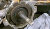
456 viewsRearward gear with original grease. The "B" means back lift box.
|
|

454 viewsHarbor Freight trim tool (nylon kit, non-scratching, less than $6) used to pry the light switch out. Very easy.
|
|
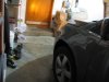
453 viewsNot great but you can see the amber of the LED turn signal as I'm standing by the rear edge of the door, about 1' away.
|
|
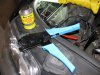
The install451 viewsLiquid electrical tape used to fill in and insulate crimps. High-quality ratcheting crimpers make the difference!
|
|
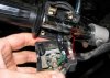
449 viewsWhen attaching the switch housing make sure to line up the housing pin to the hole in the handle bar.
|
|
| 334 files on 17 page(s) |
 |
11 | |
|





