 Most viewed - How-to Most viewed - How-to |
Reference shot448 viewsRear mounted gear box. On left side of trailer looking to the right side.
|
|
447 views
|
|
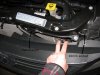
Left side shown. Right is just like the left side.447 viewsAfter removing the bumper skin fasteners remove the 10mm bolt and pin retainer. Do this for both sides (remove all fasteners). This will allow the front fascia and bumper skin to be pulled back enough to get to the head lights. The bumper is still attached to the vehicle by lower fasteners but for this situation it doesn't need to be fully removed.
|
|
447 viewsPlanetary gear in position and pin marked where it needs to be cut.
|
|
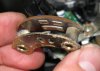
446 viewsThe female part of the sliding switch for the high/low beam switch. The long pad is the common power and the right pad is low beam, the left pad is high beam (as pictured here).
|
|
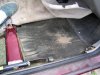
445 viewsFirst layer under right front carpet, foam padding like the rear but bonded to a protective rubber(?) sheet.
|
|
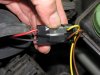
445 viewsThe plug wouldn't lock into the stock connector so I used a supplied zip-tie to bind it and electrical tape to keep it together. Notice that the RED wire mates with the YELLOW (+12 volts) bulb connector wire and the BLACK wire mates with the BROWN (ground) bulb connector wire.
|
|

High/low beam switch443 viewsThe male part of the sliding switch for the high/low beam switch.
|
|
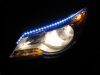
443 viewsLow beams on.
|
|
442 views
|
|
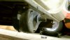
Reference shot441 viewsRear mounted gear box. On left side of trailer looking to the right side.
|
|
440 viewsThe interior.
|
|
440 views...to release it from the split shaft below, making it easy to remove the entire pin assembly without breaking it.
|
|
439 views
|
|
439 views
|
|
438 views
|
|
436 views
|
|
436 views
|
|
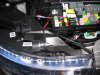
436 viewsJust testing the left DRL LED array directly to the relay box. Used the camera flash to 'dim' the LEDs so they wouldn't wash out the picture. They are so bright that it can be seen that they are on.
|
|
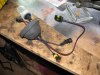
435 viewsAnother view of the completed assembly. Notice that the bulb is on the inside of the rubber boot and that the bulb is still in the container. You don't want to expose the bulb until you absolutely have to, it must stay clean! You can use rubbing alcohol to wipe the bulb down if it gets dirty or you touch it -- oil from your skin is bad for the bulb!
|
|
| 334 files on 17 page(s) |
 |
12 | |
|





