 Most viewed - How-to Most viewed - How-to |
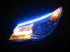
437 viewsOEM DRL on.
|
|
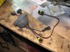
436 viewsAnother view of the completed assembly. Notice that the bulb is on the inside of the rubber boot and that the bulb is still in the container. You don't want to expose the bulb until you absolutely have to, it must stay clean! You can use rubbing alcohol to wipe the bulb down if it gets dirty or you touch it -- oil from your skin is bad for the bulb!
|
|

435 viewsHere's the high/low beam switch all buttoned up.
|
|
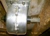
Reference shot434 viewsForward mounted gear box. On left side of trailer looking to the right side. Notice that I added a steel roll pin to the front of the gear box, just in case I need to crank from the front.
|
|
433 views
|
|
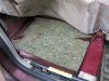
432 viewsRight rear foam padding.
|
|
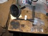
432 viewsFeed the harness through the rubber cup from the front side.
|
|
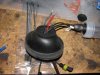
431 viewsHere's the rubber boot turned inside-out to get a better view of the inside of the gasket and the wires running through it.
|
|
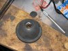
430 viewsTo hold the cover up while cutting, I used a 1/2" socket underneath. Use a very sharp Xacto blade and cut s-l-o-w-l-y and carefully.
|
|
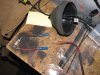
428 viewsFor the particular bulbs that came in this kit (an early version), I had to cut the wires and then feed them through the gasket. I used butt connectors and high-quality crimpers (expensive) to secure the wires.
|
|

427 viewsFacing into the sun, the LEDs can still be seen although they aren't as bright as dedicated OEM units found on other vehicles.
|
|

426 viewsThe retaining plate on top of the sliding switch assembly.
|
|

425 viewsLeft heat exchanger accordion duct, looking forward. For some reason, the diameter was more than 16" so the wrap didn't fully cover it.
|
|
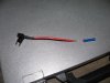
Fuse tap!425 viewsThis is how to easily and safely tap into some power without compromising the stock wiring or running a long lead through the firewall. I cut the bullet connector off so I could pass the wire through the grommet hole and so I could use one of my own spade connectors. To be on the safe side, make sure the fuse tap can handle 25A to 30A minimum. A 10A fuse tap won't work! The bottom slot is for the placing the stock fuse while the top is for the accessory and thus the red wire leading from the fuse tap.
|
|

All done!425 viewsLights on. I took this picture with the flash to dim the LED array as they are very bright.
|
|
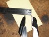
423 viewsTo make a nice 7/8" circle use a compass and set it to 7/16" (about 11mm).
|
|
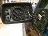
422 viewsWhat the interior looks like. I set the mirror so it was centered in the housing. I started at the 11 o'clock position and worked my way anti-clockwise (aka counter-clockwise), gently prying the mirror clips away from the ring mount.
|
|
421 views
|
|
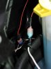
421 viewsThe red wire in the background is the turn signal tap while the white wire in the foreground is the feed to the DRL array.
|
|

420 viewsJust after sunset. At the time I took these pictures it was brighter out than what appears in the images. The LEDs are bright enough to the camera that it used a faster shutter speed, thus making the image look darker than it really is.
|
|
| 334 files on 17 page(s) |
 |
13 | |
|





