 Most viewed - How-to Most viewed - How-to |
691 views
|
|
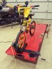
683 viewsWill even work for my son's bicycle :-)
|
|
671 views
|
|
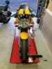
669 viewsSport bike clamped in without straps.
|
|
668 views
|
|

Mounting measurements659 viewsAll measurements are from the inside boundaries. Final measurements may slightly differ (~1/8") after bolts are tightened. This won't affect operation.
Drilling requires a 1/2" drill bit for metal. All of the holes in the vise parts are on the large side so there is a little bit of room for small tweaks in mounting positioning.
|
|
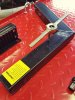
653 viewsI chased the clamp bolt holes with a tap to expose the bare metal. I opted to not use the supplied lock washers because I don't like the idea of them digging into the paint and exposing the metal to air and moisture (rust). So ALL fasteners have blue Loctite on them to hold them in place. I used a flat washer under every bolt head and under every nut.
|
|
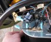
620 viewsAll connected. Use the Bentley wiring diagram to assist but this is basically how it's wired. Remember, you're simply replacing the vibrator with the VR and using a resistor pack in-line with the fuel gauge sender to bring the voltage down to a reasonable level.
+12V (black wire from gauge cluster) -> VR -> gauge -> resistor pack -> tank sender (brown w/black stripe wire)
|
|
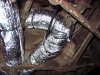
616 viewsI put a scrap piece of insulation (that I removed from the corner) under the split-loom to fully cover the duct.
|
|
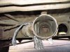
614 viewsLooking forward, this is the point where the main heater duct connects to the forward 'Y' where some heat can be diverted to the interior floor vent that is between the driver/passenger seats that points into the center of the Bus. Here the flap is closed so all heated air goes to the front of the Bus.
|
|
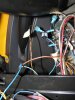
605 viewsWhat it looks like under the dash when put back together. The resistors aren't touching anything and there's no tension on them.
|
|
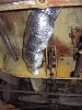
598 viewsUnder the pedal area. The section behind it isn't insulated yet...
|
|
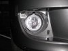
592 viewsRight fog light installed, front view. Note that adjusting screw is always at the top.
|
|
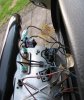
585 viewsAnother view.
|
|
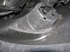
572 viewsBack side of the right fog light housing.
|
|
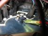
567 viewsClose up of mounting the VR to the back of the gauge body.
|
|
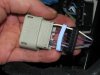
565 viewsSeparate the bottom plug (black) and the seal (light blue) within. You'll need to unwrap the black electrical tape on the wiring and throw it away. This will give you the needed slack in the wiring.
|
|
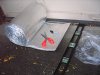
564 viewsMeasure the length needed to be wrapped, add 1/2" to 1" extra, and cut with ordinary scissors. The wrap I used was 16" and it worked well to wrap the circumference of the duct with a little over-lap. Put the over-lap seam down so if water should get in, it will drain out. I had 11" and 8" zip-ties so I used them together to hold the wrap. Snug it down until it just dimples the insulation; don't reef down on it and over-tighten it!
|
|
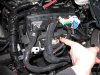
564 viewsHere's the plug to be modified. I found it unnecessary to remove ALL of the plugs per the instructions but you can. Remember to lift the red tab up to unlock the connector.
|
|
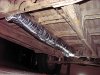
559 viewsLooking forward at the center section. I clipped off the stock duct zip-ties, wrapped the duct, and then zip-tied the duct back to the mounting points.
|
|
| 334 files on 17 page(s) |
 |
5 | |
|





