 Most viewed - How-to Most viewed - How-to |
485 views
|
|
483 views
|
|
482 views
|
|
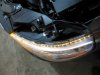
481 viewsTop view of LEDs firing.
|
|
480 viewsFlap fully open, allowing some of the heated air to divert into the center of the Bus for the rear passengers.
|
|
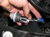
Getting the power ready for the turn signal LED array.480 viewsUse a BLUE wire tap-in like what I show. The ones that are RED are for smaller wire sizes and the YELLOW ones are for larger wires. I prefer these because when you insert the insulated male connector it makes a positive fit and keeps the tap locked on to the wire. -- Left side: Tap into the white wire with the GREEN stripe. -- Right side: Tap into the white wire with the BROWN stripe. -- FYI for both lights: The black wire [on the outside] is ground, the middle wire is the parking light and the other outside wire is the turn signal.
|
|
479 views
|
|
477 viewsHere the flapper is opened all of the way so all of the heated air goes into the Bus interior. This system is used by all the Types of engines (Type I/II, III, & IV).
|
|
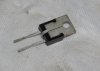
477 viewsHere's the VR. The center pin is a ground and the easiest way to ground it is to CAREFULLY bend it back onto the backside of the VR body. It will then be pressed against the gauge cluster body that is grounded. The pins are delicate and if you bend them too much they will break!
|
|

Turn signal switch477 viewsAll apart. Use white lithium on the left part of the switch, where the ball bearing rubs against the left wall. Use dielectric grease everywhere else.
|
|
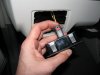
477 views...and now it's in the 'locked' position. I noticed many of the electrical connectors had some sort of lock on them. If you see a red tab/button then that's a connector lock.
|
|
477 viewsNext, I used a 15/64" (almost 6mm which would work fine) and hand drilled the hole for the grommet (yes, I twisted it with my bare fingers). I wanted to make sure I drilled straight and using a hand-held drill would've caused the hole to be at a slight angle due to the head light housing interfering with the drill chuck.
|
|
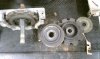
477 viewsLeft to right: Rear of gear box with rearward ring, laying on table is planetary ring, behind that is the forward ring, and behind that is a thin plastic washer.
|
|
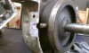
476 viewsThe pin is missing. Looks melted...??? Without this pin set in the case halves the planetary ring rotates and doesn't allow the forward gear to rotate properly.
|
|
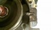
476 viewsRepaired pin cut, ground further, and beveled. Fits in the hole nicely! Remember, the planetary ring will move side-to-side so make sure the pin isn't butted against the end of the hole. Allow for the movement.
|
|
474 views
|
|
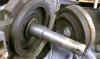
474 viewsInside of rearward gear and planetary gear mating teeth.
|
|
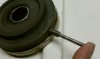
474 viewsThe new pin in the hole, ready for welding.
|
|
473 views
|
|
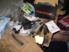
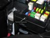
473 viewsXentec - The kit I used. Also, remove the DRL (Daytime Running Lights) relay, #173. It's located where the fuses are but a little deeper behind the dashboard -- it easily pulls straight out. Yes, you'll have to manually turn on your lights when you drive now. You can drive with the relay intact and the lights will come one (well, ours did), but the HIDs are getting a reduced voltage and may not turn on, they could even turn off while driving due to the reduced voltage feeding them. By removing the relay you insure that they get full voltage when you turn on the headlights.
|
|
| 334 files on 17 page(s) |
 |
9 | |
|





